Product Description
Excellent powder metallurgy parts metallic sintered parts
We could offer various powder metallurgy parts including iron based and copper based with top quality and cheapest price, please only send the drawing or sample to us, we will according to customer’s requirement to make it. if you are interested in our product, please do not hesitate to contact us, we would like to offer the top quality and best service for you. thank you!
How do We Work with Our Clients
1. For a design expert or a big company with your own engineering team: we prefer to receive a fully RFQ pack from you including drawing, 3D model, quantity, pictures;
2. For a start-up company owner or green hand for engineering: just send an idea that you want to try, you don’t even need to know what casting is;
3. Our sales will reply you within 24 hours to confirm further details and give the estimated quote time;
4. Our engineering team will evaluate your inquiry and provide our offer within next 1~3 working days.
5. We can arrange a technical communication meeting with you and our engineers together anytime if required.
| Place of origin: | Jangsu,China |
| Type: | Powder metallurgy sintering |
| Spare parts type: | Powder metallurgy parts |
| Machinery Test report: | Provided |
| Material: | Iron,stainless,steel,copper |
| Key selling points: | Quality assurance |
| Mould type: | Tungsten steel |
| Material standard: | MPIF 35,DIN 3571,JIS Z 2550 |
| Application: | Small home appliances,Lockset,Electric tool, automobile, |
| Brand Name: | OEM SERVICE |
| Plating: | Customized |
| After-sales Service: | Online support |
| Processing: | Powder Metallurgr,CNC Machining |
| Powder Metallurgr: | High frequency quenching, oil immersion |
| Quality Control: | 100% inspection |
The Advantage of Powder Metallurgy Process
1. Cost effective
The final products can be compacted with powder metallurgy method ,and no need or can shorten the processing of machine .It can save material greatly and reduce the production cost .
2. Complex shapes
Powder metallurgy allows to obtain complex shapes directly from the compacting tooling ,without any machining operation ,like teeth ,splines ,profiles ,frontal geometries etc.
3. High precision
Achievable tolerances in the perpendicular direction of compacting are typically IT 8-9 as sintered,improvable up to IT 5-7 after sizing .Additional machining operations can improve the precision .
4. Self-lubrication
The interconnected porosity of the material can be filled with oils ,obtaining then a self-lubricating bearing :the oil provides constant lubrication between bearing and shaft ,and the system does not need any additional external lubricant .
5. Green technology
The manufacturing process of sintered components is certified as ecological ,because the material waste is very low ,the product is recyclable ,and the energy efficiency is good because the material is not molten.
FAQ
Q1: What is the type of payment?
A: Usually you should prepay 50% of the total amount. The balance should be pay off before shipment.
Q2: How to guarantee the high quality?
A: 100% inspection. We have Carl Zeiss high-precision testing equipment and testing department to make sure every product of size,appearance and pressure test are good.
Q3: How long will you give me the reply?
A: we will contact you in 12 hours as soon as we can.
Q4. How about your delivery time?
A: Generally, it will take 25 to 35 days after receiving your advance payment. The specific delivery time depends on the items and the quantity of your order. and if the item was non standard, we have to consider extra 10-15days for tooling/mould made.
Q5. Can you produce according to the samples or drawings?
A: Yes, we can produce by your samples or technical drawings. We can build the molds and fixtures.
Q6: How about tooling Charge?
A: Tooling charge only charge once when first order, all future orders would not charge again even tooling repair or under maintance.
Q7: What is your sample policy?
A: We can supply the sample if we have ready parts in stock, but the customers have to pay the sample cost and the courier cost.
Q8: How do you make our business long-term and good relationship?
A: 1. We keep good quality and competitive price to ensure our customers benefit ;
2. We respect every customer as our friend and we sincerely do business and make friends with them, no matter where they come from.
/* March 10, 2571 17:59:20 */!function(){function s(e,r){var a,o={};try{e&&e.split(“,”).forEach(function(e,t){e&&(a=e.match(/(.*?):(.*)$/))&&1
Can chain couplings be used in high-speed applications?
Chain couplings can be used in certain high-speed applications, but there are limitations and considerations that need to be taken into account. The suitability of chain couplings for high-speed applications depends on factors such as the specific design of the coupling, the chosen chain type, and the operating conditions. Here are some key points to consider:
- Coupling Design: The design of the chain coupling plays a crucial role in determining its suitability for high-speed applications. High-speed chain couplings typically incorporate features that minimize vibration, reduce stress concentrations, and ensure smooth operation. Couplings designed for high-speed use may have additional balancing or damping mechanisms to counteract potential issues associated with centrifugal forces and resonance.
- Chain Type: The type of chain used in the coupling can affect its performance at high speeds. In general, roller chains are commonly used in chain couplings. However, for high-speed applications, special high-speed roller chains or other chain types designed for increased rotational speeds may be required. These chains are designed to minimize friction, reduce wear, and handle the centrifugal forces associated with high-speed operation.
- Bearing Selection: Proper bearing selection is critical for high-speed chain couplings. The bearings used in the coupling should be capable of handling the anticipated speeds and dynamic loads. High-quality, precision bearings with appropriate lubrication are typically necessary to ensure smooth operation and minimize the risk of premature failure.
- Balancing and Vibration: High-speed chain couplings should be properly balanced to minimize vibration and ensure stable operation. Imbalances in rotating components can lead to increased noise, excessive stress, and reduced service life. Balancing techniques such as dynamic balancing or the use of counterweights may be employed to achieve smooth and reliable operation.
- Lubrication: Adequate lubrication is crucial for high-speed chain couplings to minimize friction, reduce wear, and dissipate heat effectively. Proper lubrication practices, including the use of high-quality lubricants and regular maintenance, should be followed to ensure optimal performance and prevent premature failure.
Despite these considerations, it’s important to note that chain couplings may have practical limitations in terms of maximum allowable speeds. The specific speed limitations will depend on factors such as the coupling design, chain type, size, and the operating conditions. It is advisable to consult the manufacturer’s specifications and guidelines to determine the maximum recommended speed for a particular chain coupling.
In certain high-speed applications where chain couplings may not be suitable, alternative coupling types such as flexible disc couplings, gear couplings, or elastomeric couplings specifically designed for high-speed applications may be more appropriate. These couplings are engineered to handle the challenges associated with high rotational speeds, offering improved balance, reduced vibration, and higher speed capabilities.
Overall, when considering the use of chain couplings in high-speed applications, it is essential to carefully evaluate the specific requirements, consult with the manufacturer, and ensure that the coupling is designed and selected to operate safely and reliably at the desired speeds.
What are the key components of a chain coupling?
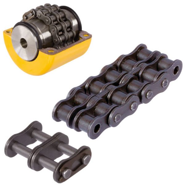
A chain coupling consists of several key components that work together to transmit power and accommodate misalignments. Here are the main components of a chain coupling:
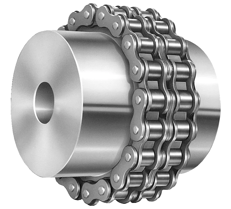
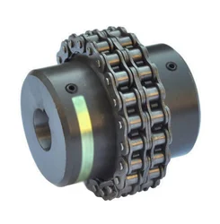
- Sprockets: Sprockets are the toothed wheels that engage with the chain. They are typically made of steel or other durable materials and have specially designed teeth that mesh with the chain rollers. The sprockets provide the driving and driven connections, transmitting torque from one shaft to another.
- Roller Chain: The roller chain is a series of interconnected links with rollers between them. It is looped around the sprockets, with the rollers engaging with the sprocket teeth. The roller chain transfers the rotational motion from the driving sprocket to the driven sprocket, allowing power transmission between the shafts.
- Connecting Pins: Connecting pins are used to join the links of the roller chain together, forming a continuous loop. These pins are inserted through the pin holes in the chain links and secured with retaining clips or other fasteners. They ensure the integrity and strength of the chain.
- Bushings or Bearings: Bushings or bearings are used to support the shafts and allow them to rotate smoothly within the chain coupling. They are typically inserted into the bores of the sprockets and provide a low-friction interface between the shaft and the coupling components.
- Guard or Cover: In some chain couplings, a guard or cover is added to enclose the sprockets and chain. This serves as a protective barrier, preventing contact with moving parts and reducing the risk of accidents or injuries. The guard or cover also helps to contain lubrication and protect the chain from contaminants.
- Lubrication: Lubrication is essential for the smooth operation and longevity of a chain coupling. Proper lubrication reduces friction, wear, and noise. Lubricants, such as chain oil or grease, are applied to the chain and sprockets to minimize frictional losses and prevent premature wear.
These components work together to provide a reliable and efficient power transmission in chain couplings. The sprockets engage with the roller chain, and as one sprocket rotates, it drives the chain, causing the other sprocket and the connected shaft to rotate. The roller chain and its components, along with lubrication, allow for flexibility and compensation of misalignment between the shafts.
What are the different types of chain couplings available?
Chain couplings come in various designs and configurations to suit different application requirements. Here are some common types of chain couplings:
- Standard Roller Chain Couplings: These are the most basic and widely used type of chain couplings. They consist of two sprockets connected by a roller chain. The sprockets have hardened teeth that engage with the chain rollers, providing a reliable power transmission. Standard roller chain couplings are generally suitable for applications with moderate torque and speed requirements.
- Double Roller Chain Couplings: Double roller chain couplings are similar to standard roller chain couplings but feature two parallel roller chains instead of one. This design increases the torque capacity and allows for higher power transmission. Double roller chain couplings are often used in applications that require higher torque and increased load-bearing capabilities.
- Silent Chain Couplings: Silent chain couplings, also known as inverted-tooth chain couplings, use a special toothed chain with a meshing sprocket design. The teeth of the chain engage with the sprocket grooves, providing a smooth and quiet operation. Silent chain couplings are commonly used in applications where noise reduction is important, such as precision machinery or equipment operating in noise-sensitive environments.
- Heavy-Duty Chain Couplings: Heavy-duty chain couplings are designed for applications that demand robust and rugged performance. They are constructed with larger sprockets and heavy-duty roller chains to handle high torque and heavy loads. These couplings are commonly used in industries such as mining, steel, and paper manufacturing, where extreme operating conditions and heavy machinery are present.
- Flexible Chain Couplings: Flexible chain couplings incorporate an elastomeric element, such as a rubber or polyurethane insert, between the sprockets and the chain. This element provides flexibility, damping, and some degree of misalignment compensation. Flexible chain couplings are suitable for applications that require shock absorption, vibration damping, and moderate misalignment tolerance.
- Stainless Steel Chain Couplings: Stainless steel chain couplings are specifically designed for applications that require corrosion resistance and sanitation, such as food processing, pharmaceutical, and chemical industries. They are made of stainless steel or other non-corrosive materials to withstand harsh environments and maintain hygienic conditions.
These are just a few examples of the different types of chain couplings available. Each type has its own advantages and is suitable for specific application requirements. It is important to carefully consider the torque, speed, misalignment, environmental factors, and other application-specific needs when selecting the appropriate chain coupling type for your particular application.


editor by CX 2024-02-04
China manufacturer Flange Cast Iron Coupling Steel Universal Joint Cardan Pump Rubber Motor Disc Curved Tooth Flex Rigid Drive Shaft Nm Yox Fluid Jaw Flexible Chain Gear Couplings
Product Description
Excellent powder metallurgy parts metallic sintered parts
We could offer various powder metallurgy parts including iron based and copper based with top quality and cheapest price, please only send the drawing or sample to us, we will according to customer’s requirement to make it. if you are interested in our product, please do not hesitate to contact us, we would like to offer the top quality and best service for you. thank you!
How do We Work with Our Clients
1. For a design expert or a big company with your own engineering team: we prefer to receive a fully RFQ pack from you including drawing, 3D model, quantity, pictures;
2. For a start-up company owner or green hand for engineering: just send an idea that you want to try, you don’t even need to know what casting is;
3. Our sales will reply you within 24 hours to confirm further details and give the estimated quote time;
4. Our engineering team will evaluate your inquiry and provide our offer within next 1~3 working days.
5. We can arrange a technical communication meeting with you and our engineers together anytime if required.
| Place of origin: | Jangsu,China |
| Type: | Powder metallurgy sintering |
| Spare parts type: | Powder metallurgy parts |
| Machinery Test report: | Provided |
| Material: | Iron,stainless,steel,copper |
| Key selling points: | Quality assurance |
| Mould type: | Tungsten steel |
| Material standard: | MPIF 35,DIN 3571,JIS Z 2550 |
| Application: | Small home appliances,Lockset,Electric tool, automobile, |
| Brand Name: | OEM SERVICE |
| Plating: | Customized |
| After-sales Service: | Online support |
| Processing: | Powder Metallurgr,CNC Machining |
| Powder Metallurgr: | High frequency quenching, oil immersion |
| Quality Control: | 100% inspection |
The Advantage of Powder Metallurgy Process
1. Cost effective
The final products can be compacted with powder metallurgy method ,and no need or can shorten the processing of machine .It can save material greatly and reduce the production cost .
2. Complex shapes
Powder metallurgy allows to obtain complex shapes directly from the compacting tooling ,without any machining operation ,like teeth ,splines ,profiles ,frontal geometries etc.
3. High precision
Achievable tolerances in the perpendicular direction of compacting are typically IT 8-9 as sintered,improvable up to IT 5-7 after sizing .Additional machining operations can improve the precision .
4. Self-lubrication
The interconnected porosity of the material can be filled with oils ,obtaining then a self-lubricating bearing :the oil provides constant lubrication between bearing and shaft ,and the system does not need any additional external lubricant .
5. Green technology
The manufacturing process of sintered components is certified as ecological ,because the material waste is very low ,the product is recyclable ,and the energy efficiency is good because the material is not molten.
FAQ
Q1: What is the type of payment?
A: Usually you should prepay 50% of the total amount. The balance should be pay off before shipment.
Q2: How to guarantee the high quality?
A: 100% inspection. We have Carl Zeiss high-precision testing equipment and testing department to make sure every product of size,appearance and pressure test are good.
Q3: How long will you give me the reply?
A: we will contact you in 12 hours as soon as we can.
Q4. How about your delivery time?
A: Generally, it will take 25 to 35 days after receiving your advance payment. The specific delivery time depends on the items and the quantity of your order. and if the item was non standard, we have to consider extra 10-15days for tooling/mould made.
Q5. Can you produce according to the samples or drawings?
A: Yes, we can produce by your samples or technical drawings. We can build the molds and fixtures.
Q6: How about tooling Charge?
A: Tooling charge only charge once when first order, all future orders would not charge again even tooling repair or under maintance.
Q7: What is your sample policy?
A: We can supply the sample if we have ready parts in stock, but the customers have to pay the sample cost and the courier cost.
Q8: How do you make our business long-term and good relationship?
A: 1. We keep good quality and competitive price to ensure our customers benefit ;
2. We respect every customer as our friend and we sincerely do business and make friends with them, no matter where they come from.
Can chain couplings accommodate axial misalignment?
Chain couplings are primarily designed to accommodate angular misalignment between the connected shafts. However, they have limited ability to handle axial misalignment, which refers to the situation where the two shafts are not perfectly aligned along their common axis.
Unlike some other types of couplings, such as flexible beam or disc couplings, chain couplings are not specifically designed to handle significant axial misalignment. The primary function of a chain coupling is to transmit torque between the shafts while allowing for some degree of angular displacement.
While chain couplings can tolerate a small amount of axial misalignment, excessive axial displacement can lead to various issues. It can cause increased stress on the coupling components, such as the roller chain, sprockets, and connecting pins, leading to accelerated wear and potential failure. Additionally, excessive axial misalignment can result in decreased power transmission efficiency and increased vibration and noise during operation.
If significant axial misalignment is anticipated in an application, it is generally recommended to consider alternative coupling options that are specifically designed to handle axial misalignment, such as double-flex or flexible beam couplings. These couplings have greater flexibility and can better accommodate axial displacement without compromising performance and reliability.
It is important to consult the manufacturer’s specifications and guidelines for the specific chain coupling being used to understand its limitations regarding axial misalignment. If axial misalignment is unavoidable, it may be necessary to implement additional measures, such as shaft guides or spacers, to minimize the impact of misalignment on the chain coupling and the connected machinery or equipment.
In summary, while chain couplings can tolerate a certain degree of axial misalignment, their primary function is to accommodate angular misalignment. Excessive axial misalignment should be avoided, and alternative coupling options should be considered if significant axial displacement is expected in an application.
What is the maximum torque capacity of a chain coupling?
The maximum torque capacity of a chain coupling can vary depending on several factors, including the size and design of the coupling, the type and quality of the components used, and the application requirements. It is important to refer to the manufacturer’s specifications and guidelines for the specific chain coupling being used. These specifications typically provide the maximum torque capacity or the maximum allowable torque for the coupling.
The maximum torque capacity is usually expressed in torque units, such as Newton-meters (Nm) or foot-pounds (ft-lb). It represents the maximum amount of torque that the chain coupling can transmit without exceeding its design limits or risking premature failure.
When selecting a chain coupling, it is crucial to consider the torque requirements of the application and choose a coupling with a sufficient torque capacity. Factors such as the power requirements, operating conditions, and misalignment tolerance should be taken into account to ensure that the selected coupling can handle the required torque.
It is important to note that exceeding the maximum torque capacity of a chain coupling can lead to various issues, including accelerated wear, excessive stress on the components, and potential coupling failure. Therefore, it is recommended to always operate the chain coupling within its specified torque limits to maintain its reliability and longevity.
For accurate and precise information regarding the maximum torque capacity of a specific chain coupling, it is necessary to consult the manufacturer’s documentation or contact the manufacturer directly. They can provide detailed information based on the specific design and specifications of the coupling.
What are the advantages of using chain couplings?
-
Flexible and Reliable Connection: Chain couplings provide a flexible and reliable connection between rotating shafts. They can accommodate misalignment between the shafts, including angular, parallel, and axial misalignments. This flexibility helps to reduce stress on the shafts and bearings, resulting in smoother operation and extended equipment lifespan.
-
High Torque Capacity: Chain couplings are capable of transmitting high torque loads. The positive engagement between the sprocket teeth and the chain rollers allows for efficient power transfer, making them suitable for applications that require the transmission of substantial rotational forces.
-
Mechanical Protection: Chain couplings act as mechanical protection by providing a breakable link in the power transmission system. In case of sudden overloads or jams in the system, the chain can break, preventing damage to the machinery components. This feature helps to protect expensive equipment and minimizes downtime for repairs.
-
Misalignment Compensation: Chain couplings can compensate for misalignment between the connected shafts. They can tolerate angular misalignment, where the shafts are not perfectly aligned at an angle, parallel misalignment, where the shafts are offset from each other, and axial misalignment, which refers to displacement along the axis of the shafts. This ability to accommodate misalignment helps to prevent excessive stress and premature wear on the shafts and bearings.
-
Wide Range of Applications: Chain couplings are versatile and find applications in various industries and machinery. They are used in conveyors, pumps, crushers, mixers, industrial drives, and many other systems. The ability to handle different torque requirements, speed variations, and misalignment conditions makes chain couplings suitable for a wide range of power transmission needs.
-
Easy Maintenance: Chain couplings are relatively easy to maintain. Regular lubrication of the chain and sprockets helps to reduce friction and wear, ensuring smooth operation and extending the life of the coupling. Maintenance tasks such as chain tensioning and inspection can be carried out without requiring complex tools or specialized training.
In summary, the advantages of using chain couplings include their flexible and reliable connection, high torque capacity, ability to compensate for misalignment, mechanical protection, wide range of applications, and ease of maintenance. These features make chain couplings a preferred choice in various industries where efficient power transmission and reliable operation are vital.
editor by CX 2023-11-06
China Professional Flange Cast Iron Coupling Steel Universal Joint Cardan Pump Rubber Motor Disc Curved Tooth Flex Rigid Drive Shaft Nm Yox Fluid Jaw Flexible Chain Gear Couplings
Product Description
Excellent powder metallurgy parts metallic sintered parts
We could offer various powder metallurgy parts including iron based and copper based with top quality and cheapest price, please only send the drawing or sample to us, we will according to customer’s requirement to make it. if you are interested in our product, please do not hesitate to contact us, we would like to offer the top quality and best service for you. thank you!
How do We Work with Our Clients
1. For a design expert or a big company with your own engineering team: we prefer to receive a fully RFQ pack from you including drawing, 3D model, quantity, pictures;
2. For a start-up company owner or green hand for engineering: just send an idea that you want to try, you don’t even need to know what casting is;
3. Our sales will reply you within 24 hours to confirm further details and give the estimated quote time;
4. Our engineering team will evaluate your inquiry and provide our offer within next 1~3 working days.
5. We can arrange a technical communication meeting with you and our engineers together anytime if required.
| Place of origin: | Jangsu,China |
| Type: | Powder metallurgy sintering |
| Spare parts type: | Powder metallurgy parts |
| Machinery Test report: | Provided |
| Material: | Iron,stainless,steel,copper |
| Key selling points: | Quality assurance |
| Mould type: | Tungsten steel |
| Material standard: | MPIF 35,DIN 3571,JIS Z 2550 |
| Application: | Small home appliances,Lockset,Electric tool, automobile, |
| Brand Name: | OEM SERVICE |
| Plating: | Customized |
| After-sales Service: | Online support |
| Processing: | Powder Metallurgr,CNC Machining |
| Powder Metallurgr: | High frequency quenching, oil immersion |
| Quality Control: | 100% inspection |
The Advantage of Powder Metallurgy Process
1. Cost effective
The final products can be compacted with powder metallurgy method ,and no need or can shorten the processing of machine .It can save material greatly and reduce the production cost .
2. Complex shapes
Powder metallurgy allows to obtain complex shapes directly from the compacting tooling ,without any machining operation ,like teeth ,splines ,profiles ,frontal geometries etc.
3. High precision
Achievable tolerances in the perpendicular direction of compacting are typically IT 8-9 as sintered,improvable up to IT 5-7 after sizing .Additional machining operations can improve the precision .
4. Self-lubrication
The interconnected porosity of the material can be filled with oils ,obtaining then a self-lubricating bearing :the oil provides constant lubrication between bearing and shaft ,and the system does not need any additional external lubricant .
5. Green technology
The manufacturing process of sintered components is certified as ecological ,because the material waste is very low ,the product is recyclable ,and the energy efficiency is good because the material is not molten.
FAQ
Q1: What is the type of payment?
A: Usually you should prepay 50% of the total amount. The balance should be pay off before shipment.
Q2: How to guarantee the high quality?
A: 100% inspection. We have Carl Zeiss high-precision testing equipment and testing department to make sure every product of size,appearance and pressure test are good.
Q3: How long will you give me the reply?
A: we will contact you in 12 hours as soon as we can.
Q4. How about your delivery time?
A: Generally, it will take 25 to 35 days after receiving your advance payment. The specific delivery time depends on the items and the quantity of your order. and if the item was non standard, we have to consider extra 10-15days for tooling/mould made.
Q5. Can you produce according to the samples or drawings?
A: Yes, we can produce by your samples or technical drawings. We can build the molds and fixtures.
Q6: How about tooling Charge?
A: Tooling charge only charge once when first order, all future orders would not charge again even tooling repair or under maintance.
Q7: What is your sample policy?
A: We can supply the sample if we have ready parts in stock, but the customers have to pay the sample cost and the courier cost.
Q8: How do you make our business long-term and good relationship?
A: 1. We keep good quality and competitive price to ensure our customers benefit ;
2. We respect every customer as our friend and we sincerely do business and make friends with them, no matter where they come from.
Can chain couplings accommodate parallel misalignment?
Yes, chain couplings are designed to accommodate a certain degree of parallel misalignment between the connected shafts. Parallel misalignment refers to the situation where the axes of the two shafts are not perfectly aligned and run parallel to each other but at a distance.
Chain couplings have some inherent flexibility that allows them to tolerate a certain amount of parallel misalignment. The flexibility is primarily provided by the roller chain, which can compensate for small parallel displacements between the shafts. This flexibility helps to reduce stress on the coupling components and allows for smooth operation even in the presence of parallel misalignment.
However, it is important to note that chain couplings have limitations in terms of parallel misalignment. Excessive parallel misalignment beyond the specified limits can lead to increased stress, uneven load distribution, accelerated wear, and potential coupling failure. The manufacturer’s specifications and guidelines should be followed to ensure that the parallel misalignment remains within the acceptable range for the specific chain coupling being used.
Proper alignment during installation is crucial to minimize parallel misalignment. The shafts should be aligned as closely as possible to ensure optimal performance and longevity of the chain coupling and the connected machinery or equipment. In some cases, additional measures such as shims or adjustable mounts may be necessary to achieve the desired alignment.
Regular inspection and maintenance of the chain coupling are also important to identify and address any parallel misalignment issues that may arise over time. If significant parallel misalignment is detected, corrective measures should be taken to realign the shafts or consider alternative coupling options that are better suited for parallel misalignment requirements.
In summary, chain couplings can accommodate a certain degree of parallel misalignment, but excessive misalignment should be avoided. Proper alignment during installation and adherence to manufacturer’s guidelines are essential for ensuring optimal performance, reliability, and longevity of the chain coupling and the connected machinery or equipment.
What are the maintenance requirements for chain couplings?
Maintaining chain couplings is essential for their reliable and efficient operation over time. Regular maintenance helps prevent premature wear, reduces the risk of unexpected failures, and prolongs the lifespan of the coupling. Here are some key maintenance requirements for chain couplings:
- Lubrication: Proper lubrication is crucial for the smooth operation of chain couplings. Regularly lubricate the roller chain and sprockets with the recommended lubricant. Follow the manufacturer’s guidelines regarding the type of lubricant to use and the frequency of lubrication. Lubrication helps reduce friction, wear, and noise, and it extends the service life of the coupling.
- Inspection: Regularly inspect the chain coupling for signs of wear, damage, or misalignment. Check the sprockets, roller chain, connecting pins, and bushings or bearings for any abnormalities. Look for worn teeth, elongation of the roller chain, loose or missing fasteners, and excessive play in the coupling. Address any issues promptly to prevent further damage and ensure the coupling’s proper functioning.
- Tension Adjustment: Check the tension of the roller chain regularly. Improper chain tension can lead to premature wear and affect the coupling’s performance. Follow the manufacturer’s guidelines for the correct chain tension and make adjustments as necessary. Proper tension ensures optimal power transmission and helps accommodate misalignments.
- Alignment: Monitor the alignment of the shafts connected by the chain coupling. Misalignment can cause excessive stress on the coupling components and lead to premature failure. If misalignment is detected, take the necessary corrective measures, such as realigning the shafts or using alignment tools. Proper alignment promotes smooth operation and prolongs the life of the coupling.
- Contamination Control: Protect the chain coupling from contamination by keeping the surrounding area clean. Dust, dirt, debris, and moisture can affect the coupling’s performance and accelerate wear. Use appropriate covers or guards to shield the coupling from external contaminants. Regularly clean the coupling and remove any debris that may have accumulated.
- Periodic Replacement: Over time, the components of a chain coupling can experience wear and fatigue. Periodically replace worn or damaged components, such as sprockets, roller chains, connecting pins, and bushings or bearings, with new ones. Follow the manufacturer’s recommended maintenance schedule for component replacement to ensure the coupling’s reliability and prevent unexpected failures.
- Documentation: Maintain proper documentation of the maintenance activities performed on the chain coupling. Keep records of lubrication schedules, inspections, adjustments, and component replacements. This documentation helps track the maintenance history of the coupling and provides valuable information for future reference and troubleshooting.
By following these maintenance requirements, you can ensure the optimal performance, longevity, and reliability of your chain coupling. Regular maintenance minimizes the risk of unexpected downtime, reduces repair costs, and maximizes the efficiency of your machinery or equipment.
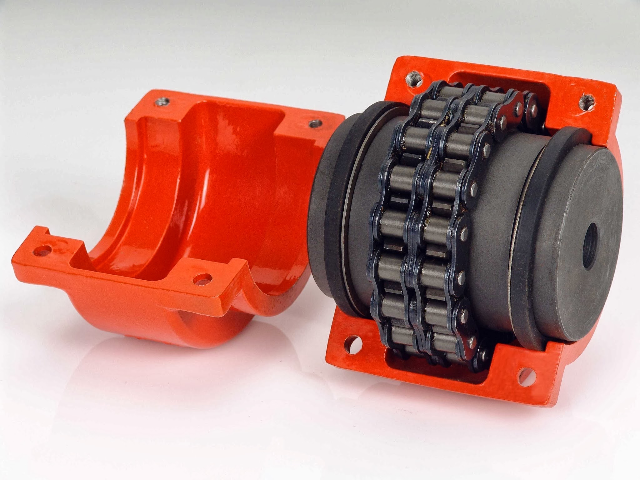
What is a chain coupling?
A chain coupling is a mechanical device used to connect two rotating shafts in a power transmission system. It consists of two sprockets or toothed wheels and a roller chain that meshes with the sprocket teeth. The sprockets are mounted on the respective shafts and linked together by the chain, allowing torque to be transmitted from one shaft to the other.
Chain couplings are designed to provide a flexible and reliable connection between shafts while accommodating misalignment between them. They are known for their ability to compensate for angular, parallel, and axial misalignments, making them suitable for a wide range of industrial applications.
The sprockets of a chain coupling typically have hardened teeth that engage with the rollers of the chain. The chain itself is made up of a series of interconnected links, each consisting of two plates joined by pins. The rollers are mounted on the pins, allowing them to rotate freely and mesh with the sprocket teeth.
One of the key advantages of chain couplings is their ability to transmit high torque loads. The engagement between the sprockets and the chain provides a positive drive, allowing for efficient power transfer even in demanding applications. Chain couplings are commonly used in heavy-duty machinery and equipment where large amounts of power need to be transferred, such as conveyors, mixers, crushers, and industrial drives.
Chain couplings also offer flexibility in shaft alignment. They can compensate for angular misalignment, which occurs when the shafts are not perfectly aligned at an angle. Additionally, they can accommodate parallel misalignment, where the shafts are offset from each other, as well as axial misalignment, which refers to the displacement along the axis of the shafts.
Proper lubrication is essential for the efficient operation and longevity of chain couplings. Lubricants such as oil or grease are applied to the chain and sprockets to reduce friction and wear. This helps to prevent heat buildup and ensures smooth rotation and power transmission.
Chain couplings are available in various sizes, configurations, and materials to suit different application requirements. The selection of a chain coupling depends on factors such as torque capacity, speed, shaft diameter, and misalignment tolerance.
In summary, chain couplings provide a flexible, reliable, and high-torque solution for connecting rotating shafts in power transmission systems. They offer the ability to compensate for misalignment, making them suitable for a wide range of industrial applications where efficient power transfer is crucial.
editor by CX 2023-09-13
China best Flexible disc couplings for stepmotors coupling and uncoupling a trailer
Structure: Disc
Flexible or Rigid: Flexible
Regular or Nonstandard: Common
Substance: Aluminium
Model Amount: Fx-DC1
Mounting: Clamp variety
Coloration: Sliver white
Certification: ISO9001:2000
Ideal advantage: Zero backlash
Min dia.: 5mm-24mm
Max dia.: 10mm-40mm
Max velocity: 10000rpm
Certificate: ISO 9001:2000
Packaging Particulars: Industrial plastic bag + regular export carton or as per customer’s ask for.
Port: Xihu (West Lake) Dis.g, ZheJiang
Fx-DC1-Single disc clamp variety shaft coupling
Materials: Aluminum,metal,metal,plastic,and so on.
End: blacken,phosphate-coat,and oxidation.
Feature
Applications:
Power transmission to industrial tools this sort of as pumps, gear containers, compressors, blowers, mixers, and conveyors a variety of mechanical and hydraulic fields
Coupling Quality Management
» Critical raw materials inspection» Stringent management above the complete producing process» Sampling of all the items after final inspection ahead of shipment» Good quality trace right after supply.
Packaging & Supply
Industrial plastic bag + regular export carton or as per customer’s request.
Shipping and delivery Detail:7 to 10 Times
Purchasing example:
Fx-DC1-L
Forex-DC1: clamp variety disc shaft coupling
30: shaft coupling outer diameter
11: shaft coupling internal diameter
fifteen: shaft coupling interior diameter
35L: shaft coupling duration
Dimention table:
Associated product photo:
Coupling Connected Types
| Shaft coupling sort | Coupling dimensions sequence |
| Jaw shaft coupling | Fx-JC series |
| Rigid shaft coupling | Forex-RC series |
| Disc shaft coupling | Forex-DC sequence |
| Flexible shaft coupling | Forex-FC sequence |
| Oldham shaft coupling | Forex-OC collection |
| Bellows shaft coupling | Fx-BC sequence |
Coupling Positive aspects
one. Tiny dimension, reduced bodyweight, high transmitted torque
2. Elastomers manufactured of polyurethane with shore hardness in between eighty-98
three.Lower noise
4.Effortless assembly
five. Compensating the axial relative drift, buffer and vibration reduction
6. Bore tolerance ISO standard H7
7. Keyway tolerance as for each DIN6885/1 JS9
eight The couplings call for no lubrication and supply very trustworthy support for mild, medium,and hefty responsibility electrical motor and inside combustion energy transmission purposes.
Coupling Manufacturing Process
Firm benefits:
one) Seasoned and specialist revenue personnel
two) The 6 Year’s exporting experience3) Rigorous top quality control system with perfect amenities
four) Sophisticated production facilities
five) The plentiful ability of R&D
6) Large&New Tech business,minimal carbon omission and environment pleasant
7) OEM approved
We would like to provide the best for you:
Superb Quality: Stringent top quality manage program and great top quality test engineer group.
Competitive Cost: Factory wholesale value.
Superb Service: Quick speed, higher effectiveness, consider our ideal to satisfy our consumers needs.
Expert Support: More than 6 years OEM service experience ,we can make in accordance to your needs.
Fast Shipping: Large inventory and 1-10 times guide time.
Calculating the Deflection of a Worm Shaft
In this article, we’ll discuss how to calculate the deflection of a worm gear’s worm shaft. We’ll also discuss the characteristics of a worm gear, including its tooth forces. And we’ll cover the important characteristics of a worm gear. Read on to learn more! Here are some things to consider before purchasing a worm gear. We hope you enjoy learning! After reading this article, you’ll be well-equipped to choose a worm gear to match your needs.
Calculation of worm shaft deflection
The main goal of the calculations is to determine the deflection of a worm. Worms are used to turn gears and mechanical devices. This type of transmission uses a worm. The worm diameter and the number of teeth are inputted into the calculation gradually. Then, a table with proper solutions is shown on the screen. After completing the table, you can then move on to the main calculation. You can change the strength parameters as well.
The maximum worm shaft deflection is calculated using the finite element method (FEM). The model has many parameters, including the size of the elements and boundary conditions. The results from these simulations are compared to the corresponding analytical values to calculate the maximum deflection. The result is a table that displays the maximum worm shaft deflection. The tables can be downloaded below. You can also find more information about the different deflection formulas and their applications.
The calculation method used by DIN EN 10084 is based on the hardened cemented worm of 16MnCr5. Then, you can use DIN EN 10084 (CuSn12Ni2-C-GZ) and DIN EN 1982 (CuAl10Fe5Ne5-C-GZ). Then, you can enter the worm face width, either manually or using the auto-suggest option.
Common methods for the calculation of worm shaft deflection provide a good approximation of deflection but do not account for geometric modifications on the worm. While Norgauer’s 2021 approach addresses these issues, it fails to account for the helical winding of the worm teeth and overestimates the stiffening effect of gearing. More sophisticated approaches are required for the efficient design of thin worm shafts.
Worm gears have a low noise and vibration compared to other types of mechanical devices. However, worm gears are often limited by the amount of wear that occurs on the softer worm wheel. Worm shaft deflection is a significant influencing factor for noise and wear. The calculation method for worm gear deflection is available in ISO/TR 14521, DIN 3996, and AGMA 6022.
The worm gear can be designed with a precise transmission ratio. The calculation involves dividing the transmission ratio between more stages in a gearbox. Power transmission input parameters affect the gearing properties, as well as the material of the worm/gear. To achieve a better efficiency, the worm/gear material should match the conditions that are to be experienced. The worm gear can be a self-locking transmission.
The worm gearbox contains several machine elements. The main contributors to the total power loss are the axial loads and bearing losses on the worm shaft. Hence, different bearing configurations are studied. One type includes locating/non-locating bearing arrangements. The other is tapered roller bearings. The worm gear drives are considered when locating versus non-locating bearings. The analysis of worm gear drives is also an investigation of the X-arrangement and four-point contact bearings.
Influence of tooth forces on bending stiffness of a worm gear
The bending stiffness of a worm gear is dependent on tooth forces. Tooth forces increase as the power density increases, but this also leads to increased worm shaft deflection. The resulting deflection can affect efficiency, wear load capacity, and NVH behavior. Continuous improvements in bronze materials, lubricants, and manufacturing quality have enabled worm gear manufacturers to produce increasingly high power densities.
Standardized calculation methods take into account the supporting effect of the toothing on the worm shaft. However, overhung worm gears are not included in the calculation. In addition, the toothing area is not taken into account unless the shaft is designed next to the worm gear. Similarly, the root diameter is treated as the equivalent bending diameter, but this ignores the supporting effect of the worm toothing.
A generalized formula is provided to estimate the STE contribution to vibratory excitation. The results are applicable to any gear with a meshing pattern. It is recommended that engineers test different meshing methods to obtain more accurate results. One way to test tooth-meshing surfaces is to use a finite element stress and mesh subprogram. This software will measure tooth-bending stresses under dynamic loads.
The effect of tooth-brushing and lubricant on bending stiffness can be achieved by increasing the pressure angle of the worm pair. This can reduce tooth bending stresses in the worm gear. A further method is to add a load-loaded tooth-contact analysis (CCTA). This is also used to analyze mismatched ZC1 worm drive. The results obtained with the technique have been widely applied to various types of gearing.
In this study, we found that the ring gear’s bending stiffness is highly influenced by the teeth. The chamfered root of the ring gear is larger than the slot width. Thus, the ring gear’s bending stiffness varies with its tooth width, which increases with the ring wall thickness. Furthermore, a variation in the ring wall thickness of the worm gear causes a greater deviation from the design specification.
To understand the impact of the teeth on the bending stiffness of a worm gear, it is important to know the root shape. Involute teeth are susceptible to bending stress and can break under extreme conditions. A tooth-breakage analysis can control this by determining the root shape and the bending stiffness. The optimization of the root shape directly on the final gear minimizes the bending stress in the involute teeth.
The influence of tooth forces on the bending stiffness of a worm gear was investigated using the CZPT Spiral Bevel Gear Test Facility. In this study, multiple teeth of a spiral bevel pinion were instrumented with strain gages and tested at speeds ranging from static to 14400 RPM. The tests were performed with power levels as high as 540 kW. The results obtained were compared with the analysis of a three-dimensional finite element model.
Characteristics of worm gears
Worm gears are unique types of gears. They feature a variety of characteristics and applications. This article will examine the characteristics and benefits of worm gears. Then, we’ll examine the common applications of worm gears. Let’s take a look! Before we dive in to worm gears, let’s review their capabilities. Hopefully, you’ll see how versatile these gears are.
A worm gear can achieve massive reduction ratios with little effort. By adding circumference to the wheel, the worm can greatly increase its torque and decrease its speed. Conventional gearsets require multiple reductions to achieve the same reduction ratio. Worm gears have fewer moving parts, so there are fewer places for failure. However, they can’t reverse the direction of power. This is because the friction between the worm and wheel makes it impossible to move the worm backwards.
Worm gears are widely used in elevators, hoists, and lifts. They are particularly useful in applications where stopping speed is critical. They can be incorporated with smaller brakes to ensure safety, but shouldn’t be relied upon as a primary braking system. Generally, they are self-locking, so they are a good choice for many applications. They also have many benefits, including increased efficiency and safety.
Worm gears are designed to achieve a specific reduction ratio. They are typically arranged between the input and output shafts of a motor and a load. The two shafts are often positioned at an angle that ensures proper alignment. Worm gear gears have a center spacing of a frame size. The center spacing of the gear and worm shaft determines the axial pitch. For instance, if the gearsets are set at a radial distance, a smaller outer diameter is necessary.
Worm gears’ sliding contact reduces efficiency. But it also ensures quiet operation. The sliding action limits the efficiency of worm gears to 30% to 50%. A few techniques are introduced herein to minimize friction and to produce good entrance and exit gaps. You’ll soon see why they’re such a versatile choice for your needs! So, if you’re considering purchasing a worm gear, make sure you read this article to learn more about its characteristics!
An embodiment of a worm gear is described in FIGS. 19 and 20. An alternate embodiment of the system uses a single motor and a single worm 153. The worm 153 turns a gear which drives an arm 152. The arm 152, in turn, moves the lens/mirr assembly 10 by varying the elevation angle. The motor control unit 114 then tracks the elevation angle of the lens/mirr assembly 10 in relation to the reference position.
The worm wheel and worm are both made of metal. However, the brass worm and wheel are made of brass, which is a yellow metal. Their lubricant selections are more flexible, but they’re limited by additive restrictions due to their yellow metal. Plastic on metal worm gears are generally found in light load applications. The lubricant used depends on the type of plastic, as many types of plastics react to hydrocarbons found in regular lubricant. For this reason, you need a non-reactive lubricant.


editor by czh